Hello!

Xaudia offer microphone re-ribboning and repair services.

2010/09/19

Microphone of the month - Old Czech tube mic: Tesla?

This is the first 'Microphone of the Month' blog, featuring classic or unusual microphones. Hopefully I'll manage to find time each month for this!

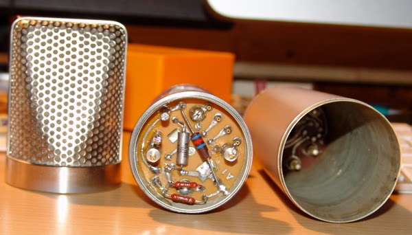
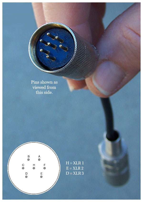
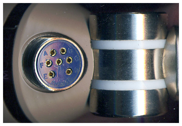
This old Czech tube microphone - a recent ebay find - may well have been made by Tesla. The capsule is connected using a connector that can also be found on old Tesla and Phillips microphones. Some of the capacitors are also made by Tesla, who were a large state owned electronics company in communist Czechoslovakia.

The 'Tesla' looks very much like an imitation of the Neumann / Gefell CMV563 bottle mic. In fact the microphone is smaller in diameter than the CMV, has no output transformer and has an unbalanced output. Like the CMV, the capsule may be swapped, and presumably other polar patterns were available. This one is marked with a red circle, which probably means omnidirectional. (I have yet to test the capsule).

The amplifier is a very simple grounded cathode amplifier, based around a Soviet 6Ж1Л (6Z1P) tube, which is a small signal pentode similar to EF95. These are also found in some Lomo and Oktava microphones, including the Lomo 19a9 and Oktava MKL2500.

Without the original power supply we can only speculate on the operating voltages. However, a B+ supply of 90V would be a good place for experiments to start - this would give a voltage on the capsule of around 60, and a sensible current through the tube circuit.

2010/08/26

Tube mic circuits - Connecting the capsule 2

Last week's technical article talked about different methods of connecting a condenser capsule to the grid of a tube amplifier, in order to build a tube mic. In this part we consider how to connect a capsule with two diaphragms in order to get a multi-pattern mic.


First let’s examine the different pickup patterns available. There are three extremes: Omni, where the microphone hears sounds equally in all directions.  Cardioid (heart shaped*), where sensitivity is greatest in the direction in which the microphone is pointing, falling off to a null point behind. And Figure-of-Eight, with equal (but opposite) pickup in front and behind, and null pickup to the sides.  To complicate things further, the pickup pattern may depend upon the frequency, and some mics will have good directionality at higher frequencies, but become less directional as the frequency drops.

But what if we want a microphone with selectable pattern? This can be achieved by arranging a pair of cardioid capsules back-to-back, and combining there signals in different ways. We’ll call these capsules front and back, although of course they could be pointing in any direction. If we require a cardioid signal, we just take the front capsule and for omnidirectional pickup, we mix both signals equally. If we want figure of eight, we subtract the output of the rear from the front: where the signals overlap at the sides of the microphone, they cancel each other out producing null points. Other patterns such as hyper-cardioid and super-cardioid may be considered as in-between positions of these extremes.

So, what is the best way to achieve this practically in our hypothetical tube microphone? Two of the earliest commercial mics with more than one pattern were the Neumann U47, which offered cardioid and omni, and the U48, with cardioid & fig. 8. Let’s look at the U47, as this is probably the simplest way to combine the two capsules.


In the U47 the front diaphragm is grounded through a 100 Meg grid resistor, and the backplate of the microphone’s dual diaphragm is polarised with about 60V, providing the potential difference required. The rear diaphragm is connected to a switch. When the switch is open, the rear capsule is left floating and only the front cardioid diaphragm is active. When the switch is closed, the rear capsule adds its contribution to the front, making an omnidirectional microphone.

What about the U48? We have seen above that if we require figure of 8 instead of omnidirectional, we must subtract, rather than add, the sounds from the rear. To do this we must invert the polarity of the rear diaphragm by reversing its relative charge. So, rather than grounding the rear diaphragm, we must raise the potential by 60V** above the backplate, and 120V above the front capsule! This is easily achieved by using the HT supply to the anode of the tube, but creates another problem. We can’t simply connect the two diaphragms because they are now at different potentials, and so a blocking capacitor must be used. The circuit looks like this:


Finally, to make the microphone have variable pattern, we simply need to make a supply that is adjustable from 0V to 120V, and apply that to the backplate. Alternatively, the signal may be taken from the backplate, through a capacitor to the tube grid.  The Neumann-Gefell UM57 does it exactly this way, with the pattern selector in the power supply.

*Really more kidney shaped, and in some languages this is the word used.
**  In fact the U48 operates around 50V / 100V.

Further reading: The G7 page at Gyraf.dk

2010/08/18

Tube mic circuits - Connecting the capsule part 1.

Even in the simplest of tube microphone circuits, there are different approaches to connecting the microphone capsule to the tube. Let's use a single-sided microphone capsule as our starting point.

The capsule behaves as a variable capacitor, changing its capacitance in response to changes in air pressure (i.e. sound). In order to generate a signal, the capsule needs to be polarised by some voltage, creating a difference in potential between the diaphragm and the back plate. This is the first decision that needs to be made - should the polarising voltage be applied to the diaphragm or the capsule backplate?

In the circuit shown on the left, the backplate of the microphone is polarised at 60V, which is obtained from the B+ supply, via a resistive divider and a small capacitor to stabilise and filter the polarising voltage. The membrane is connected directly to the tube grid, and a high value resistor (Rg, typically 100 kΩ to 1000 kΩ) connects both the grid and the membrane to ground. We have our potential difference across the membrane, and the sensitivity of the mic may be adjusted by increasing and decreasing the polarisation voltage. As the capacitance of the capsule changes in response to sound, a tiny current will flow through Rg, and this signal is amplified by the tube.

An example of this arrangement may be seen in the Neumann Gefell M582.


In some cases the grid resistor may be omitted. In the circuit below, which appeared in an article in Tape Op magazine by Dave Royer, the capsule diaphragm is grounded by grid leakage rather than a 'real' resistor. It works perfectly.


This simple arrangement is not possible when the capsule backplate is mechanically (and electrically) connected to the body of the microphone. In this case the diaphragm must be polarised directly.

However, having a voltage of around 60V on the tube grid this would adversely change the operating points of the tube circuit, and so a capacitor must be used to block the DC voltage (left). Some listeners claim to hear the difference between different types of capacitors, and so normally a very high quality type should be used in this position. An additional high value polarising resistor is also required, otherwise the high impedance audio signal would be attenuated through the stabilisation cap.

An example of this method of connection is the Neumann-Gefell CMV563, which is designed to be used with bayonette style capsules such as the M7, M8 and M9.

Sometimes it is the membrane which is connected directly to the body, such as in this Teladi K120. The approach is the same as the circuit above.


In my next post I'll consider how to connect mic capsules with two membranes, and how to combine them to generate different polar patterns.

2010/07/21

Unknown German Prototype Tube Microphone - 'The Unbekannt"

Unknown German tube microphone
Here is a recent Ebay find. It's an unbranded tube microphone, and judging from the components probably from the 1960s, in what was formerly West Germany. We've called it the 'Unbekannt', which is simply German for 'unknown'. The amplifier circuit is a 3 stage unbalanced transformerless design, using EF40 pentode and an ECC81 twin triode. The final stage is a cathode follower.

The schematic is here.

As is so often the case, the microphone has been separated from the original power supply, so it is not possible to say what the exact operating voltages would have been. However, the voltage divider for the capsule polarisation may give us a clue - 2 Meg and 400K would be a simple way of using a 240V supply to put 40V on the capsule.

The metalwork is nicely done, and is comparable to Reissmann, Thiele and Teladi microphones of similar age. It seems too well constructed to be a DIY mic, but the oddball range of parts makes us think that it is some prototype from one of the microphone makers of the era.

The capsule is quite unusual, but sadly is missing a diaphragm at the moment. It uses springs and screws to adjust the tension and space to the back plate, so this can be adjusted after installation. We'll try to get that up and running very soon so we can see what it sounds like!

2010/06/13

Lomo 19a9 tube mic manual


Here is a scan of the original Russian manual for the LOMO 19a19 tube microphone.


The full schematics for the 19a9 have been hard to find, particularly the power supply. I’ve saved those schematics as separate files. Click here to see them. I’ve combined the key components for the microphone circuit in the figure below.


There is a discussion about the microphone here at Group DIY.

2010/06/08

Thiele microphone brochure

Thiele M5 tube microphone


Here’s a scan of a short advertising document for Thiele M4 and M5 (photo to the left) tube microphones. 


Theile sales document

Note how expensive the microphones were at the time - 500 and 600 Deutchmarks. For reference, between 1950 and 1960, 4 Deutchmarks approximately equalled 1 US dollar.

2010/06/07

Syncron AU7A microphones Part 2

Last time I wrote about a pair of Syncron AU7A microphones. The capsules were in good condition, but the batteries had leaked, causing corrosion and damage to the circuit. For one of these mics I decided to fit a tube circuit based on a 6205 subminiature tube (5840* would do just as well or better)**.

Tube modified Syncron microphone circuit, 6V regulated heater supply omitted.

The Syncron capsule operates happily between about 40V and 60V, and a simple voltage divider was used to supply the backplate with a suitable polarising voltage. As the capsule is cardioid only, the circuit can be made as simple as possible, and there is no need for a capacitor between the diaphragm and the tube grid.


With a little creative hacking I was able to reuse the circuit board to construct a valve circuit, which avoids damaging the microphone further. Although physically larger, the tube sits where the transistor was (I even used the same PCB pads as the FET), and there is room on the underside of the board for a couple of capacitors. An added bonus is that the original transformer is quite suitable for use in a tube circuit, and was rewired in 10:1 configuration. The rest of the circuit - 5 resistors and another cap - fit on the 'wrong' side of the board in the cavity below the capsule housing. Then it is a simple case of wiring the connector to the circuit and connecting the capsule, taking care not to damage the diaphragm.


One thing to look out for with this arrangement is that the amphenol cable plug & connector on the microphone are the reverse of the normal gender, which means that there can be 110V DC on the exposed pins. Consequently care must be taken to connect the microphone before the power supply is turned on, otherwise a short sharp shock can happen. Of course this isn't really an acceptable acceptable solution from a safety point of view.

In practice the microphone works very nicely and is suitably quiet for recording vocals. We tracked some female vocals with it yesterday and it performed very well in that application.

Meanwhile, I have managed to track down some 22V batteries from Farnell, which should be suitable for the capsule polarisation, so I'll attempt to restore the second mic to its original state. More on that soon.

** With hindsight the 5840 may be a better bet as there is an internal connection between the cathode and grid 3. This allows you to cut off two of the leads, which means using up one less precious pad on the circuit board inside - space is tight!

**Readers familiar with the 'Royer' tube circuit will recognise the topology, although a few of the component values are different.

Xaudia blog post on phantom power for these mics.

2010/06/06

Syncron AU7A (Fairchild F/22) microphones Part 1


I was lucky enough to come across a pair of Syncron AU7A microphones (aka Fairchild F/22) on ebay. On arrival from the US I found that all the foam lining in the boxes had decomposed and spread black dust everywhere. Luckily the capsules appeared to be in fine condition, and the mics came with the original cables, so the should be a good chance of getting them back to working condition.


That's easier said than done! The mics run on 4 batteries - 2 x 4.2V for the amplifier and 2 x 21V for the polarisation. Unfortunately, our microphones came complete with the original vintage batteries inside, which had inevitably leaked and caused corrosion throughout. The batteries are now pretty much unobtainable, so I used a bench voltage supply to simulate the batteries. Microphone number one gave a very weak and noisy (hiss) signal - I suspected the FET had somehow become contaminated by the battery acids. Mic 2 was slightly better, but certainly not something you could use as a serious recording tool.

These are reported to be the first commercially available FET microphone, and searching the internet didn't throw up any schematics so I traced out the circuit, which is very very simple - capsule -> field effect transistor -> DC blocking cap -> transformer.

EDIT 21/9/2011 : please note that the schematic posted here contained errors. A revised version is here!

The transformer may be wired either for 200 or 50 ohms, and measurement showed it has a voltage ratio of 5:1 in series or 10:1 in parallel mode.

At this stage I needed to make a decision on how to get the best out of the microphone. More on that very soon, but for now here are some web links to Syncron information - there's not a lot of it about!

2010/02/16

Neumann Gefell UM57 experiments

Lately I've had the opportunity to play around with several vintage Neumann Gefell tube microphones - a CMV563 (below with UM70 capsule) , a M582 and a pair of UM57s.


These all have broadly similar circuits, with a EC92 tube and transformer coupled feedback. The UM57 is configured for different polar patterns, whereas with the CMV563 and M582 you have to swap the capsule. There are other differences - the schematics are shown here.

One particularly common fault with examples of these microphones is that the original electrolytic output capacitor can dry out with age. This is by no means always the case, and the capacitor in the UM57 on the left above was in perfect condition after nearly 50 years!  The one on the right has been replaced with an orange modern metalised film capacitor.

So what is the effect of ageing of this capacitor? As the electrolyte dries out, the absolute value of the capacitance drops, which will affect the frequency response of the valve amplifier inside the microphone. To simulate this, a capacitance decade box was wired in place of the output capacitor (C3), and the chart below shows how the frequency response changes as the capacitance decreases in 0.2 uF steps.*

Part of the circuit is shown inset within the chart. Although intuitively we expect the smaller capacitor to give us less bottom end, the network of the capacitor, transformer primary winding and resistor acts as a resonant filter, producing a peak in the bass region just above a sharp drop off. The human ear can perceive this as more bass - although not necessarily in a good way: the microphone may seem muddy or lack clarity.

So, having a good quality capacitor here is vital, and the value of this can be used to tweak the bass response if desired. Of course this analysis is just for the tube circuit inside the mic and does not consider the effects of ageing on the capsule itself - that's a story for another day.

SJT Feb 2010

* Measured using a swept-sine wave from 1Hz to 48KHz.

2010/02/12

Beautiful girls in Milton, Wisconsin

beautiful SE555 space echo
This is the label on a reverb pan found inside a vintage Roland Space Echo SE555. “Manufactured by beautiful girls in Milton, Wisconsin, under controlled atmosphere conditions." Right! And you thought they were made in Japan by robots, didn’t you?

Recording with the Josephson C720

Back in August we were lucky enough to get our hands on a special edition Josephson C720 microphone for the studio, one of only 20 made in the first production run, and having lived with this for nearly half a year it’s probably about time we reviewed it.

josephson C720 microphone

The first thing you notice about the C720 is its size - this is one big mic, U47-big, and makes a big bold statement in the live room or vocal booth - it’s built like a tank and it definitely has that ‘wow’ factor which gets the artists talking.

The next thing that grabs your attention is its radical aluminium metal-foam headbasket, which looks like something you could scrub your pots and pans with. The non-periodic headbasket is actually designed to eliminate internal acoustic reflections and refraction of soundwaves, avoiding comb-filtering effects and so giving a more realistic recording.

The third thing you notice is that it has two XLR outputs. Like many condenser microphones, the capsule has dual diaphragms which can be combined in different combinations to give cardioid, omni, figure of eight patterns. Unlike most microphones, the two transducers have separate head amplifiers and separate outputs which means that the signals from opposite sides of the microphone can be recorded separately and mixed together, either in phase or with the polarity reversed, at a later stage. What this innovation means in practice is that you can pick the polar pattern after recording, which might be used to eliminate unwanted sound sources by rotating the null point of the microphone. Also, and more importantly in our studio use, with close-mic’ed sources such as vocals you can dial in more or less proximity effect, making a singer seem bigger, darker or lighter and brighter.

So what does it sound like? Possibly because of the lack of head basket comb filtering, and the facility to tune the pattern and proximity effect, this is a very versatile microphone. The one word that sprang to my mind in describing the sound, whichever pattern you pick, is ‘solid’.*

Another thing we’ve noticed is it sounds pretty damned good on pretty much anything you can throw at it. Because of it’s ability to handle high sound pressure levels and become a go-to mic for low end stuff, and is rock-solid on bass guitar and front of kick drum, but it’s just as handy on both male and female vocals - especially those with a tendency to get loud when they belt it out. Vocal recordings are up front, sound as they should, but without the top end brightness of, say, our TLM49.

Furthermore, it can be used for more radical effects by compressing or reverberating one side of the capsule only. For example, I had some interesting results on a male rock vocal by compressing the signal from the front capsule, mixing together with the phase reversed rear capsule, then compressing the sum of these. The effect was that as the vocals push harder, the relative amount of rear capsule included becomes greater giving it more of a hypercardioid pattern, balancing the tendency of the vocalist to step back from the mic when belting it out. With a bit of creativity the possibilities are endless.

Overall this is a brilliant, radical piece of thinking and and one of those bits of gear that comes into your life and is there to stay.

*After writing this I read another review of this mic which used exactly the same word - ‘solid’ - to sum up the sound.


2010/01/07

New Toy!

AVO MkIII tube testerHere is our new pride and joy - a 1960's AVO mkIII valve characteristic meter. It's built like a tank, with wonderful vintage knobs and dials. And comes in handy for getting those amps and mics up and running.

2010/01/05

Teladi tube mic

Teladi K120 tube microphone

And here's something altogether nicer. It's an old Teladi end-address tube mic, probably from the 1950s. Construction wise, it feels very Gefell, with a small metal (nickel?) diaphragm and a U47 style connector.

I sketched out the schematic here....

Teladi K120 traced schematic


2010/01/04

Cheap!

Broadly speaking, you get what you pay for.

Over the past 5 years or so the market has become saturated wth inexpensive made-in-china microphones which have brought condenser mics within the budget of home studios and, along with computer based recording, have arguably revolutionised the recording industry. But there has to be some corner cutting or trade-off in component quality or quality control, doesn't there? I picked this SE electronics 'miniSE' up on ebay for £40, which brings it in at about 15 times cheaper than the ex-demo Neumann TLM49 we bought earlier in the year. Like the neumann it is a cardioid-only transformerless mic. And unlike the Neumann, this came in a nice aluminium carrying case (as opposed to cardboard!)

On opening the case, I found the mic was rattling. 2 minutes with a screwdriver revealed that the capsule had not been properly screwed down. Also you can see that the circuit board is covered in flux. The capsule looks exactly the same as the CK12 copies found in MXL2001 mics and others. I've seen several of these now with bumps and wrinkles in the membrane. The metalwork is actually quite nice, so it may get one of the spare AKG capsules and a new circuit transplanted.

Update: Eventually I used this body for a DIY ribbon mic!

2010/01/03

Wetzel microphone on the bench


Here's a nice little tube mic for restoration. The manufacturer is Joachim Wetzel of Liepzig and looks to date from the 50s or 60s.
It is currently undergoing a recap and the capsule will be reskinned. The head amp is based on an ECC83, with two triode gain stages. There's something funny going on with this one. The power supply voltages are somewhat low, and it seems like the old diode rectifiers are causing problems. More on this later.


2010/01/02

Framus Television


Framus Television

It is quite sad to think that the success of the big American guitar manufacturers (F--, G--, you know who you are!) led not only to some excellent instruments and high standards of construction, but also to the demise of several smaller builders of quality guitars. Cheap imports from the East added to the problem. One such victim was the German manufacturer Framus, who went bankrupt and ceased production at the end of the '70s. (The company has since been reborn).

Framus made guitars of generally high quality with some interesting features. Here is a 1968 Framus Television semi-acoustic, the shape of which is clearly influenced by Fender's Jaguar/Jazzmaster (or was it the other way round?) . It has a pleasing asymmetry, with a single f-hole (as far as we can tell, most Televisions had two), three pickups, and a tremolo. The headstock shape is whacky - like a big hand - but we like it. Colour of this one is a beautiful stained carrot-orange-yellow, rather like certain Gretschs - we think they call this 'aniline yellow'. It has a laminate top and back.


This guitar arrived on the bench with toggle switches in place of the original sliders, as well as a couple of loose wires, which we of course replaced/fixed. The circuit is slightly unusual (which is why it is on this website at all!), so we've sketched a circuit diagram to help other owners.

Framus Television circuit

The circuit consists of two parallel output stages each with volume and tone pots (marked T&V in the diagram) , which the player may use to switch between 'rhythm' and 'lead' settings. This approach predates the days when everyone has booster pedals on the floor, and similar systems are also found on Jaguars and Jazzmasters. In the 'rhythm' position, only the neck pickup is active. In the 'lead' position any combination of the three pickups may be switched on - the pickups in combination give some audible phase cancellation. There is also a bass cut filter switch. A summary of the switches:

S1 = Bridge pickup on/off
S2 = Middle pickup on/off
S3 = Neck pickup on/off
S4 = Bass cut (lead circuit only)
S5a = Sends neck pickup to rhythm or lead tone/volume circuit.
S5b = Switches between lead and rhythm tone/volume circuits.

As the tone and volume pots are tricky to remove and function well, they were not investigated or measured for value. I think they are just standard.
There's a good chance that the circuit is similar to Strato Delux models of similar vintage, which also have up to 5 switches. Do let us know if you can confirm or deny this.

2010/01/01

G7 microphone


Jakob Erland’s Gyraf G7 DIY tube mic project has proved one of the most popular microphone projects. Several years ago I built a pair of these from scratch, and have since built several variations using different tubes, transformers etc. Below are a few notes on the project.


1. Using a single sided capsule


When using a single sided capsule, the circuit can be simplified somewhat and several parts omitted. The the capsule may be wired straight to the tube grid, avoiding use of a coupling cap. Note that this affects the polarity of the mic, so reverse the output wires and be sure to check against an SM57 or similar know microphone! In this arrangement, the backplate polarisation resistor can be lower than 1 gig.


2. Some measured voltages:
I built a version of the microphone by etching Gyraf's layout. Wired it up and checked some voltages - and found that the supply is rather low under load. I got about 176 Volts without the mic connected, and was down to 136 V with the mic in the loop. Heater supply dropped from 6.3V (set whilst unloaded) to 6.08V. Here are some voltages for reference.


3. Better matching of the capsule polarisation voltages.

Note in the diagram above that one side of the capsule has a slightly higher voltage than the other - no problem in omni or cardioid but noticeable in figure8 mode when recording Blumlein pairs. Here's a quick fix!