Last month I posted about a pair of Ward Beck Systems preamps that I had stripped down ready for racking. Finally the chassis arrived from Canford Audio, so off we go again...

The old aluminium front plates from the preamp modules were screwed to the new front panel to act as a drill guide, so getting the holes in the right places was quite easy (for once). The Canford chassis is very nice to work with - the aluminium panels machine easily, and the metal is thick and sturdy enough for the job.

With additional holes drilled for XLR inputs and a power switch, the panel is ready for the modules to be screwed in place.

It looks like a neat job once the black printed control panels and all the knobs are back in place - I also added a pair of jack sockets as additional outputs so that I can route the signal to either the front of the unit or the studio patchbay - or both for some parallel compression fun!
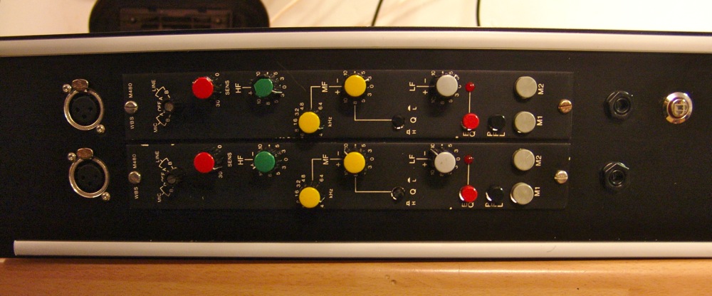


However, when we wire it that way the polarity of the preamp is inverted, as shown on the scope.

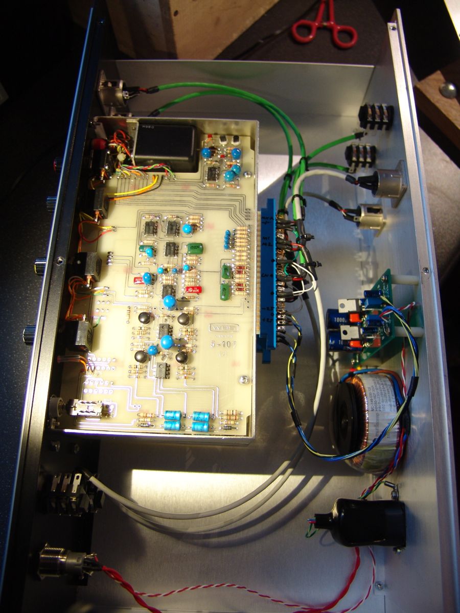
The hole for the fused IEC power inlet was cut through with an appropriate punch - this gives a neater rectangle than a jigsaw or just drilling and filing, and is quicker too. A dual ±24V bipolar supply is required, and I used a small board left over from an 1176 project. The board from mnats.net uses LM317 and LM337 voltage regulators, and 5Kohm trimmers were used to set the voltages. The modules have on-board filters and regulators to bring the down to ±18V, and their is no audible hum on these modules even at full gain.
Once up and running, the modules sound very nice with plenty of gain. I particularly like the low boost on the EQ, which sounds like it should be useful for beefing up tracks. At the moment many of the pots are rather worn and scratchy, so I next will strip it all down and replace those. It never stops!

No comments:
Post a Comment
Post a comment!
Note: only a member of this blog may post a comment.