Hello!

Xaudia offer microphone re-ribboning and repair services.

2010/06/13

Lomo 19a9 tube mic manual


Here is a scan of the original Russian manual for the LOMO 19a19 tube microphone.


The full schematics for the 19a9 have been hard to find, particularly the power supply. I’ve saved those schematics as separate files. Click here to see them. I’ve combined the key components for the microphone circuit in the figure below.


There is a discussion about the microphone here at Group DIY.

2010/06/08

Thiele microphone brochure

Thiele M5 tube microphone


Here’s a scan of a short advertising document for Thiele M4 and M5 (photo to the left) tube microphones. 


Theile sales document

Note how expensive the microphones were at the time - 500 and 600 Deutchmarks. For reference, between 1950 and 1960, 4 Deutchmarks approximately equalled 1 US dollar.

2010/06/07

Syncron AU7A microphones Part 2

Last time I wrote about a pair of Syncron AU7A microphones. The capsules were in good condition, but the batteries had leaked, causing corrosion and damage to the circuit. For one of these mics I decided to fit a tube circuit based on a 6205 subminiature tube (5840* would do just as well or better)**.

Tube modified Syncron microphone circuit, 6V regulated heater supply omitted.

The Syncron capsule operates happily between about 40V and 60V, and a simple voltage divider was used to supply the backplate with a suitable polarising voltage. As the capsule is cardioid only, the circuit can be made as simple as possible, and there is no need for a capacitor between the diaphragm and the tube grid.


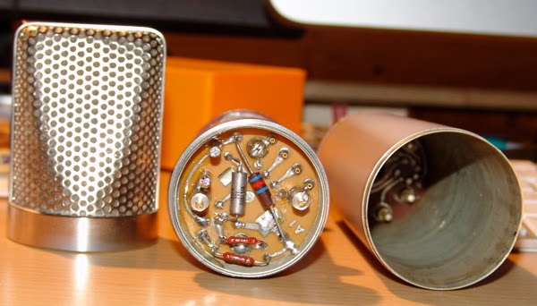
With a little creative hacking I was able to reuse the circuit board to construct a valve circuit, which avoids damaging the microphone further. Although physically larger, the tube sits where the transistor was (I even used the same PCB pads as the FET), and there is room on the underside of the board for a couple of capacitors. An added bonus is that the original transformer is quite suitable for use in a tube circuit, and was rewired in 10:1 configuration. The rest of the circuit - 5 resistors and another cap - fit on the 'wrong' side of the board in the cavity below the capsule housing. Then it is a simple case of wiring the connector to the circuit and connecting the capsule, taking care not to damage the diaphragm.


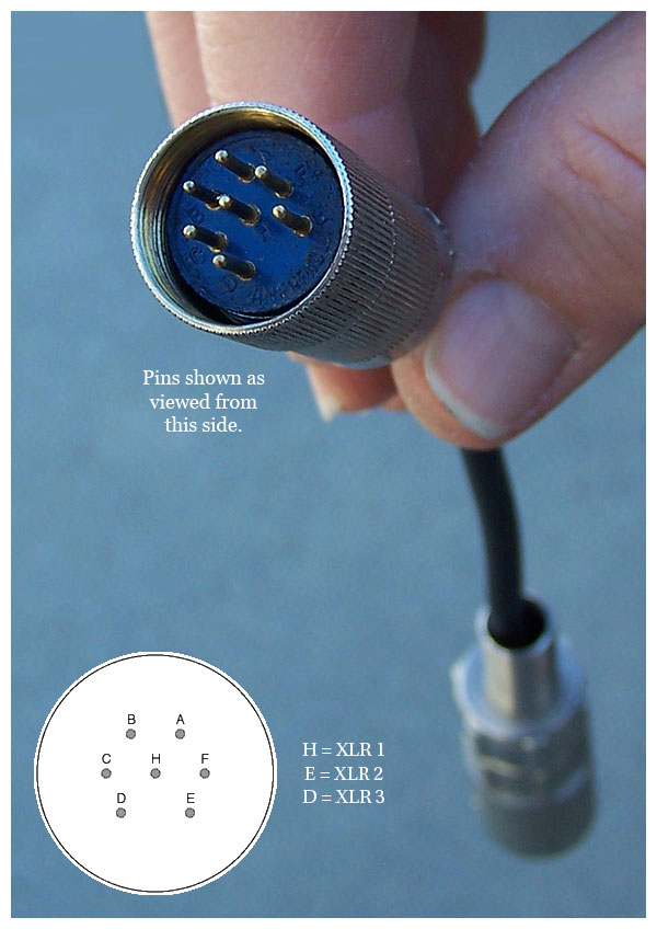
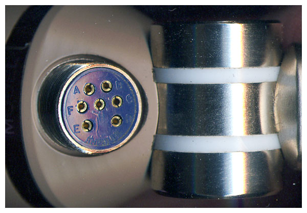
One thing to look out for with this arrangement is that the amphenol cable plug & connector on the microphone are the reverse of the normal gender, which means that there can be 110V DC on the exposed pins. Consequently care must be taken to connect the microphone before the power supply is turned on, otherwise a short sharp shock can happen. Of course this isn't really an acceptable acceptable solution from a safety point of view.

In practice the microphone works very nicely and is suitably quiet for recording vocals. We tracked some female vocals with it yesterday and it performed very well in that application.

Meanwhile, I have managed to track down some 22V batteries from Farnell, which should be suitable for the capsule polarisation, so I'll attempt to restore the second mic to its original state. More on that soon.

** With hindsight the 5840 may be a better bet as there is an internal connection between the cathode and grid 3. This allows you to cut off two of the leads, which means using up one less precious pad on the circuit board inside - space is tight!

**Readers familiar with the 'Royer' tube circuit will recognise the topology, although a few of the component values are different.

Xaudia blog post on phantom power for these mics.

2010/06/06

Syncron AU7A (Fairchild F/22) microphones Part 1


I was lucky enough to come across a pair of Syncron AU7A microphones (aka Fairchild F/22) on ebay. On arrival from the US I found that all the foam lining in the boxes had decomposed and spread black dust everywhere. Luckily the capsules appeared to be in fine condition, and the mics came with the original cables, so the should be a good chance of getting them back to working condition.


That's easier said than done! The mics run on 4 batteries - 2 x 4.2V for the amplifier and 2 x 21V for the polarisation. Unfortunately, our microphones came complete with the original vintage batteries inside, which had inevitably leaked and caused corrosion throughout. The batteries are now pretty much unobtainable, so I used a bench voltage supply to simulate the batteries. Microphone number one gave a very weak and noisy (hiss) signal - I suspected the FET had somehow become contaminated by the battery acids. Mic 2 was slightly better, but certainly not something you could use as a serious recording tool.

These are reported to be the first commercially available FET microphone, and searching the internet didn't throw up any schematics so I traced out the circuit, which is very very simple - capsule -> field effect transistor -> DC blocking cap -> transformer.

EDIT 21/9/2011 : please note that the schematic posted here contained errors. A revised version is here!

The transformer may be wired either for 200 or 50 ohms, and measurement showed it has a voltage ratio of 5:1 in series or 10:1 in parallel mode.

At this stage I needed to make a decision on how to get the best out of the microphone. More on that very soon, but for now here are some web links to Syncron information - there's not a lot of it about!