Hello!

Xaudia offer microphone re-ribboning and repair services.

2011/01/11

Thread Adapters for RCA, Sony and other microphones

RCA to modern mic stand thread adapter
A few months ago I was trying to find some thread adapters for a customer with an old RCA junior ribbon microphone, who wanted to use it with a modern standard 5/8" microphone stand. Most suppliers were charging around $25 dollars, plus post and the inevitable import and handling duties.

So we decided to make some.

These fit most of the 'big' vintage RCA microphones, including the 44, 74b and 77 ranges, and also are perfect for Sony professional mics, including the C38b, FV300 and C48 microphones. They also fit Syncron AU7A / Fairchild F22 microphones, and several other American and Japanese microphones with a large thread.

Update:
These are now for sale on the Xaudia website priced at £6.00.

If you want one, please get in touch.

2011/01/09

Japanese Auction Poetry

Unintended poetry, via translation of a Japanese auction.

It is a rare thing. It is a microphone,
I kept it as collection with a thing handed over before,
The movement had sound then.

But the measurement performance in the new thing is unidentified,
Because I do not make the measurement whether you appear,
Attached to the measurement data of 43 years and 44 years.

The one that has, thanking you in advance,
The one that I want even as for such thing, thanking you in advance,
Because there are a wound and a scratch.

Please understand used goods and ask after above contents,
Understanding in clay,
I do the question as far as I understand it, but answer.

It is communication after the end, but contacts the first on the next morning,
Sorry by a private affair, but thanking you in advance,
Of the one that I am very sorry, but new one and evaluation remarkably have worse.

I will delete, although being really selfish,
In addition, if communication seem to be three days late, please let me know,
I cancel it and I do it.

It is measured for there to be many successful bids of the one,
Where I cannot totally accept communication recently,
Be heated, and there is not it with the state of things really anymore.

But please understand it, and that which I never want,
Please let me know because I do not mind a question and a business,
In addition, please let me know when communication becomes slow.

I am really selfish, but approve it.

Unintentionally written by Coldbreak9, 2011

False Economy a.k.a. "I can't afford to buy cheap."

Here's a little lesson that I learned (again) recently. Buying cheap, used equipment can cost just as much, or more, than buying new.

RE20 microphone in the Xaudia studio
I recently found an ElectroVoice PL20 microphone for sale on a forum for $200, which translates as about £130. The PL20 is exactly the same (apart from the colour) as the much loved RE20, which is a perfect choice for recording drums, bass, vocals, brass and many other instruments. Considering that these microphones generally go for around £400 here in the UK, I thought I would grab a bargain for our studio. Even with transatlantic postage, duty, and maybe some small repairs, I should come out ahead of the game, right?

WRONG!

The first thing that arrived was a letter demanding a whopping payment of duty and handling for the import.

On unpacking I noticed that the microphone rattled - the capsule was loose. This is actually a common fault with these microphones - the foam disintegrates and the capsule becomes loose. Luckily, replacement foam is available for a small charge from Shuttlesound. I ordered a kit and it arrived the next day.

Time for surgery: Here is an excellent photo-journal showing how to open up an RE20.

The mic comes apart easily - you need to unscrew the XLR connector at the bottom (note the screw turns counter-intuitively), and unsolder it , then undo the hex nut behind it. This reveals the wiring which can be fed through the mic body so the capsule may be withdrawn.

Also remove the grill, which will unscrew once a small grub screw has been removed. On this mic the hexagonal hole had been stripped round, and so I had to carefully drill this out and re-tap the thread.

With the mic apart I unsoldered the capsule, cleaned out dirt and deteriorated foam, and then put it all back together again with the new foam for testing.

The capsule was no longer loose, but the mic still rattled! Something was broken inside the capsule assembly.

I took it apart again and took the top cover off the capsule. Inside I could see that the small black baffle behind the diaphragm had become unglued. This is not good - it can't be reached without removing the diaphragm, and this is like brain surgery.

With nothing to lose, I carefully unsoldered and removed the diaphragm with a scalpel, then re-glued the baffle and reversed the process, and tested. Sadly the 'repaired' capsule had low bass response. It was time to admit defeat and order a new capsule, which did indeed solve the problem. The mic is now back to full working order, and sounds just like the other RE20s.

Total cost:
'Bargain' microphone: £130
International postage: £25
Duty and handling £49!
New foam set + delivery + VAT: £23
New capsule + VAT: £167
+ a couple of hours ordering and fitting bits.

Total = £394

For reference,  Thomann.de sell a package for £399 which includes an RE20, a stand and 10M cable.

Lesson learned.... at least for now.

Oh, and the mic stand clip is missing....

2011/01/08

Mic Of The Month: Sony F-V300 Dynamic microphone

Sony F-V300 and C38b microphones
This unusual Sony microphone (left) looks like the younger brother of a C38b (right) or maybe a C48 condenser mic, and shares the same high build quality and some hardware components with these mics. But in actual fact this is a high quality cardioid pattern dynamic microphone, model F-V300.

Inside, the microphone is very simple, with just a capsule in the top compartment, and the on/off switch and transformer wired to a printed circuit board below. The fixed grey output cable looks to be the same type as found on the C38b.
The capsule is suspended from 8 small springs to act as an internal shockmount, which seems to work well, in conjunction with the yoke, to acoustically decouple the microphone element.
This example has some traces of foam around the element, indicating that an internal windshield has at some time been removed.

The label states that the mic is nominally of 1kΩ impedance, although in practice seems lower than this and it has no problems driving standard low-Z microphone preamps. The output is strong and clear across the range, and the output is similar in level and detail to a healthy EV RE20, although with a more pronounced proximity effect.

As far as we know, this microphone was only marketed in Japan, but if you have any information to confirm or deny this, or in fact any information about this mic at all, please let us know!


UPDATE 22/2/11
This microphone has become a bit of a favourite for guitar cabs - it seems to have just the right amount of   proximity boost for that application, giving clear and solid presence to the lower end. It also makes a decent tom mic.

2011/01/07

Strange things you find inside ribbon mics (part 1)

Microphone ribbons are generally made from very thin metal foil, and aluminium is the ideal material as it is very light but also very conductive. The output of the microphone is inversely proportional to mass, and so a thicker, heavier ribbon will give a lower output, and a thin light ribbon will be more sensitive. Many manufacturers use something typically around 0.0001 inch or 2 microns in thickness. The ribbon is also typically corrugated either along the full length to prevent lateral motion, or at the ends to give a 'piston' style of ribbon. Well, that is how it should be.

However, ultra-thin aluminium is hard to get hold of, and the non-specialist may be tempted to make repairs using materials that are more readily available. Here are some things I have found inside microphones masquerading as ribbons - needless to say they were all replaced with good quality aluminium foil of an appropriate thickness!

1. Cigarette Paper.

This microphone actually worked, to an extent! It at least made a sound. The ribbon was made from an old fag packet.
Cigarette packs used to come lined with paper-backed foil - I've never been a smoker so I don't really know why, but I imagine for freshness or something. The foil is thin and already textured - it just needs to be separated from the paper. Actually this last part seems to be optional, and sometimes bits of paper are still attached, making the ribbon heavy and noisy.

1.b I've heard that chewing gum wrappers were also used for redneck ribbons, if you want a minty fresh microphone.

1.c Here's a lovely example of cigarette paper being used for a ribbon in an old GEC microphone.


2. Kitchen Foil

Kitchen foil is easy to handle, yet much too thick to make a decent ribbon. But that doesn't stop people trying. This is a common ebay trick... the ribbon looks in good condition, but when the mic arrives the output is low and sounds crunchy.

3. Sweet Wrappers
Plastic coated foil or metallised plastic, like that found in sweet wrappers is an interesting innovation, but is generally too heavy and has too high a resistance to make a decent ribbon. Also the plastic doesn't conduct. This microphone gave almost no signal, and it isn't hard to see why.

2010/12/21

Microphone of the Month - Philips Ribbon Mic


This old microphone by Philips came from a seller in Egypt - I have a vision of it being used back in the 1940s and 50's, broadcasting out in the desert, near the Pyramids and Sphinx....

The mic was in pretty bad shape and in need of a full restoration. The ribbon was broken, and it was missing a yoke and several other parts. However, it's a pretty interesting microphone and so gets to be our microphone of the month for December.

This microphone appears to be based closely on Harry F. Olson's drawings in early patents and presented in the Journal of the Society of Motion Picture Engineers, back in 1931.


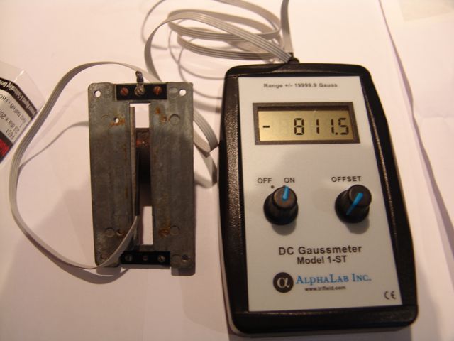
The magnetic field is provided by one large permanent barrel magnet. This microphone had a measured field of about 1200 Gauss between the poles, with ribbon dimensions of 5.5 mm wide by 67 mm long.

The original ribbon - sadly very oxidised - was of the piston type, with corrugations at each end and a flat section in the middle region. On closer inspection, the ribbon appears to have been designed for in-field replacement: each end is terminated in a thicker, silver-plated fold of foil, with a hole drilled for 'easy' mounting (easy being a relative term in this case). The ribbon is held in place with two brass clamps, each mounted held in place with a singe screw. The disadvantage of using a single screw rather than a pair for the ribbon clamps is that the clamp has a tendency to rotate as it is tightened, which can distort or wreck the ribbon. The clamps are soldered to wires which run to the transformer primary, and these wires are doubled (or tripled) in each case, presumably to keep resistance noise to a minimum.

With a rewire and a new (corrugated) ribbon the microphone works and sounds rather full and rich. However, the output transformer is wound for high impedance output, and won't drive a standard mic preamp - so the microphone benefits from using an active buffer or an impedance matching transformer. Hum is also an issue with this, despite the massive brass housing.

I haven't seen another one like this - either in life or on the web. If you have any further information on this, I'd love to hear from you.

2010/12/02

Fun with magnets and an Electrovoice V1 velocity ribbon mic

Here's an early Electrovoice velocity ribbon mic, model V1. These are great looking microphones, but the early versions are rather crudely made and this one, like many others, suffered from low output due to weakened magnets.

Bob Crowley has a few things to say about these mics - not all of them nice!

The motor of this model is based on a single cylindrical permanent magnet, clamped to a pair of metal plates which make up the pole pieces of the assembly. Because of the positioning of the magnet, the magnetic field is uneven, with a significant difference in field between the top and bottom of the motor assembly. In our example we found that the field varied from around 700 gauss at the bottom to 1000 gauss at the strongest point. This is very low for a ribbon mic, and, along with the oxidised ribbon is responsible for a low, noisy output.

Fortunately, we have sourced some very powerful cylindrical N42 neodynium magnets of a suitable size and shape, which are a perfect replacement for the original weak magnet.


With the new magnet the field is increased by a factor of around four, to about 3000-3200 gauss, a much healthier figure which should lead to an increased output and much improved signal-to-noise performance.


Now it's time to cut a new ribbon, reassemble the microphone, and do some listening tests. In the meantime, we made a rather attractive bracelet from some of the spare magnets.

2010/12/01

Cat Mac Attack!


Pansy the cat has got it in for the MacBook, and launches surprise attacks like this, usually whilst I'm writing an important email, a blog entry, or leaving feedback on ebay.

At least it explains the spelling!

2010/11/28

Winter is here! And so are Modern Day Chicane.

This was the scene at Xaudia studio yesterday - a beautiful cold, crisp and bright day in North Yorkshire, and it's times like this you really appreciate the peace & tranquility we get here. Ideal for creativity and recording. And this was the view from the studio over the surrounding fields.

We're a little isolated, not quite in the middle of nowhere, but certainly just down the road from the middle. They don't grit the road here, and sometimes the pipes freeze, but yesterday everything was perfect.

Modern Day Chicane were here to record some drum tracks for a future EP, in what turned out to be a productive, if somewhat frantic session. I arrived early to mic up the kit as drummer Pete was coming up from London on the train, which of course arrived a little late due to the weather, which left us about 4 hours to get the drum takes. We tracked at a blistering pace, cutting six live versions that may (or may not) see the light of day as bonus tracks, then we did five of the songs again to a click track, with Ryan and Nicola (pictured) in the control room providing guide vocals, guitar and bass.

Once we had a couple of decent takes of each drum track, we abandoned the editing and packed up early because it was getting cold and dark, and the talent had to get to a gig. It had already dropped to -4︒C by the time we had to scrape the ice from the cars. Brrr!

I went home and lit the fire!

2010/11/25

Mic of the Month - RCA Junior ribbon mics

October was a bad month for blogging - I was busy with the haunted house sound installation, and this was compounded by a fault with my Macbook, which took the Apple repair centre three weeks to find and fix, a long time to track down a faulty cable. With a microphone, that would be the first thing to check! Amongst all the chaos I completely forgot to do the 'mic of the month' column.


Back in the real world, I have chosen the RCA Junior ribbon for November's Mic of the Month. This is because they seem popular at the moment, and we've seen four at the workshop for service or repair. The fun thing about this family of microphones is that they vary somewhat in construction, so it is possible to compare and contrast versions from different eras. They tend to be a bit more affordable than the bigger RCA 44 and 77 mics, but still have a good tone that is very usable in a modern studio, especially if the ribbon is in good condition and the transformer is healthy and wired correctly.


The 'Junior' was created as a budget version of the RCA44, with a similar motor assembly but smaller magnets and housing. The most commonly seen models are the 'black badge' and 'red badge' versions, and these are actually quite different inside - the black badge model has a 3.0 mm x 55 mm ribbon, whilst the red badge version I examined has a wider, 4.5 mm ribbon and a stronger magnetic field.


The output transformers on these microphones can be set for 50 Ohm, 250 Ohm or 10KOhm output impedance, and it is worth checking that the mic is wired correctly to get the best performance with modern studio equipment. Normally that will be the 250 ohm setting.

The earliest and rarest version, the MI-4010-A, is shown on the right in the picture below. It is slightly larger than the later versions, with a different ribbon assembly which has horseshoe style magnets around the back of the ribbon. The magnetic field in this example is weaker, and the output lower than the more modern versions, although the tone with a new 1.8 micrometer ribbon is very pleasing. 


Finally, some RCA mics were actually made in Europe, and it would seem that some appear under different names. The microphone on the left is badged as 'Magneti Marelli, Milano, Italy' but is almost identical to the black badge RCA 74b. The only difference is that the Magneti has an alternative transformer, but still with high and low impedance options. The sound is every bit as good.


We'd love to hear from anyone who knows more about the Magneti Marelli microphones and their relationship with RCA.

(Thanks to Jules at DADA Studios in Belgium and Jørn Christensen at Rodeløkka Studio in Norway.)

2010/11/16

Drew Stephenson - A Driven Man is (Finally) Here

Almost two years ago, singer-songwriter Drew Stephenson and Cellist Hilary Jones started recording an album in our studio. Anyway, after what seems like a very long time, Drew's album "A Driven Man is Coming" will be released on November 19th at a free launch gig in York. The gig will be at 1331, on Grape Lane. More details can be found at Drew's website.

Support comes from Dan Webster.

Do come and join us if you can.

2010/11/02

Sounds from the halloween maze


The big 'Hallowscream' event at York Maze is now over for the year, and the guys and girls are now hurridly getting ready for Guy Fawkes night. It's a quick turn around so good luck!

Several people asked to hear the sounds that we 'created' for the two Halloween haunted houses. I took most of the sounds from the Freesound Project, which is a very handy searchable library of sounds, most of which are available through the Creative Commons license scheme. Other sounds used were my own creations.

The creepy clown theme for the 'CarnEvil' haunted house was based on a loop from The Midnight Syndicate, who specialise in music for haunted house and similar attractions. Some of their tracks were also used for background music in the theatre area.

I'll leave these tracks up for a week or so, so grab them quickly. Enjoy!

Carnevil Haunted House


Boiler Room

Barnegeddon

Toilet Lobby
(A mash-up of Beethoven, Mozart, and some C&W in the background!)

2010/10/31

Halloween? Hallowscream


For a change, I have spent most of October fitting speakers and providing the sounds for the Halloween events at York Maze close to our studio, and now it's all up and running - we had over 1000 people through the gate last night and are expecting even more this evening. The two haunted houses are excellent scary fun, and the creepy clown music will worm its way into your brain and keep you up all night.

A couple of people have asked for clips of the music from the haunted houses, and I'll try to post those up tomorrow.

2010/09/19

Microphone of the month - Old Czech tube mic: Tesla?

This is the first 'Microphone of the Month' blog, featuring classic or unusual microphones. Hopefully I'll manage to find time each month for this!

This old Czech tube microphone - a recent ebay find - may well have been made by Tesla. The capsule is connected using a connector that can also be found on old Tesla and Phillips microphones. Some of the capacitors are also made by Tesla, who were a large state owned electronics company in communist Czechoslovakia.

The 'Tesla' looks very much like an imitation of the Neumann / Gefell CMV563 bottle mic. In fact the microphone is smaller in diameter than the CMV, has no output transformer and has an unbalanced output. Like the CMV, the capsule may be swapped, and presumably other polar patterns were available. This one is marked with a red circle, which probably means omnidirectional. (I have yet to test the capsule).

The amplifier is a very simple grounded cathode amplifier, based around a Soviet 6Ж1Л (6Z1P) tube, which is a small signal pentode similar to EF95. These are also found in some Lomo and Oktava microphones, including the Lomo 19a9 and Oktava MKL2500.

Without the original power supply we can only speculate on the operating voltages. However, a B+ supply of 90V would be a good place for experiments to start - this would give a voltage on the capsule of around 60, and a sensible current through the tube circuit.

2010/08/26

Tube mic circuits - Connecting the capsule 2

Last week's technical article talked about different methods of connecting a condenser capsule to the grid of a tube amplifier, in order to build a tube mic. In this part we consider how to connect a capsule with two diaphragms in order to get a multi-pattern mic.


First let’s examine the different pickup patterns available. There are three extremes: Omni, where the microphone hears sounds equally in all directions.  Cardioid (heart shaped*), where sensitivity is greatest in the direction in which the microphone is pointing, falling off to a null point behind. And Figure-of-Eight, with equal (but opposite) pickup in front and behind, and null pickup to the sides.  To complicate things further, the pickup pattern may depend upon the frequency, and some mics will have good directionality at higher frequencies, but become less directional as the frequency drops.

But what if we want a microphone with selectable pattern? This can be achieved by arranging a pair of cardioid capsules back-to-back, and combining there signals in different ways. We’ll call these capsules front and back, although of course they could be pointing in any direction. If we require a cardioid signal, we just take the front capsule and for omnidirectional pickup, we mix both signals equally. If we want figure of eight, we subtract the output of the rear from the front: where the signals overlap at the sides of the microphone, they cancel each other out producing null points. Other patterns such as hyper-cardioid and super-cardioid may be considered as in-between positions of these extremes.

So, what is the best way to achieve this practically in our hypothetical tube microphone? Two of the earliest commercial mics with more than one pattern were the Neumann U47, which offered cardioid and omni, and the U48, with cardioid & fig. 8. Let’s look at the U47, as this is probably the simplest way to combine the two capsules.


In the U47 the front diaphragm is grounded through a 100 Meg grid resistor, and the backplate of the microphone’s dual diaphragm is polarised with about 60V, providing the potential difference required. The rear diaphragm is connected to a switch. When the switch is open, the rear capsule is left floating and only the front cardioid diaphragm is active. When the switch is closed, the rear capsule adds its contribution to the front, making an omnidirectional microphone.

What about the U48? We have seen above that if we require figure of 8 instead of omnidirectional, we must subtract, rather than add, the sounds from the rear. To do this we must invert the polarity of the rear diaphragm by reversing its relative charge. So, rather than grounding the rear diaphragm, we must raise the potential by 60V** above the backplate, and 120V above the front capsule! This is easily achieved by using the HT supply to the anode of the tube, but creates another problem. We can’t simply connect the two diaphragms because they are now at different potentials, and so a blocking capacitor must be used. The circuit looks like this:


Finally, to make the microphone have variable pattern, we simply need to make a supply that is adjustable from 0V to 120V, and apply that to the backplate. Alternatively, the signal may be taken from the backplate, through a capacitor to the tube grid.  The Neumann-Gefell UM57 does it exactly this way, with the pattern selector in the power supply.

*Really more kidney shaped, and in some languages this is the word used.
**  In fact the U48 operates around 50V / 100V.

Further reading: The G7 page at Gyraf.dk

2010/08/18

Tube mic circuits - Connecting the capsule part 1.

Even in the simplest of tube microphone circuits, there are different approaches to connecting the microphone capsule to the tube. Let's use a single-sided microphone capsule as our starting point.

The capsule behaves as a variable capacitor, changing its capacitance in response to changes in air pressure (i.e. sound). In order to generate a signal, the capsule needs to be polarised by some voltage, creating a difference in potential between the diaphragm and the back plate. This is the first decision that needs to be made - should the polarising voltage be applied to the diaphragm or the capsule backplate?

In the circuit shown on the left, the backplate of the microphone is polarised at 60V, which is obtained from the B+ supply, via a resistive divider and a small capacitor to stabilise and filter the polarising voltage. The membrane is connected directly to the tube grid, and a high value resistor (Rg, typically 100 kΩ to 1000 kΩ) connects both the grid and the membrane to ground. We have our potential difference across the membrane, and the sensitivity of the mic may be adjusted by increasing and decreasing the polarisation voltage. As the capacitance of the capsule changes in response to sound, a tiny current will flow through Rg, and this signal is amplified by the tube.

An example of this arrangement may be seen in the Neumann Gefell M582.


In some cases the grid resistor may be omitted. In the circuit below, which appeared in an article in Tape Op magazine by Dave Royer, the capsule diaphragm is grounded by grid leakage rather than a 'real' resistor. It works perfectly.


This simple arrangement is not possible when the capsule backplate is mechanically (and electrically) connected to the body of the microphone. In this case the diaphragm must be polarised directly.

However, having a voltage of around 60V on the tube grid this would adversely change the operating points of the tube circuit, and so a capacitor must be used to block the DC voltage (left). Some listeners claim to hear the difference between different types of capacitors, and so normally a very high quality type should be used in this position. An additional high value polarising resistor is also required, otherwise the high impedance audio signal would be attenuated through the stabilisation cap.

An example of this method of connection is the Neumann-Gefell CMV563, which is designed to be used with bayonette style capsules such as the M7, M8 and M9.

Sometimes it is the membrane which is connected directly to the body, such as in this Teladi K120. The approach is the same as the circuit above.


In my next post I'll consider how to connect mic capsules with two membranes, and how to combine them to generate different polar patterns.

2010/07/21

Unknown German Prototype Tube Microphone - 'The Unbekannt"

Unknown German tube microphone
Here is a recent Ebay find. It's an unbranded tube microphone, and judging from the components probably from the 1960s, in what was formerly West Germany. We've called it the 'Unbekannt', which is simply German for 'unknown'. The amplifier circuit is a 3 stage unbalanced transformerless design, using EF40 pentode and an ECC81 twin triode. The final stage is a cathode follower.

The schematic is here.

As is so often the case, the microphone has been separated from the original power supply, so it is not possible to say what the exact operating voltages would have been. However, the voltage divider for the capsule polarisation may give us a clue - 2 Meg and 400K would be a simple way of using a 240V supply to put 40V on the capsule.

The metalwork is nicely done, and is comparable to Reissmann, Thiele and Teladi microphones of similar age. It seems too well constructed to be a DIY mic, but the oddball range of parts makes us think that it is some prototype from one of the microphone makers of the era.

The capsule is quite unusual, but sadly is missing a diaphragm at the moment. It uses springs and screws to adjust the tension and space to the back plate, so this can be adjusted after installation. We'll try to get that up and running very soon so we can see what it sounds like!

2010/06/13

Lomo 19a9 tube mic manual


Here is a scan of the original Russian manual for the LOMO 19a19 tube microphone.


The full schematics for the 19a9 have been hard to find, particularly the power supply. I’ve saved those schematics as separate files. Click here to see them. I’ve combined the key components for the microphone circuit in the figure below.


There is a discussion about the microphone here at Group DIY.

2010/06/08

Thiele microphone brochure

Thiele M5 tube microphone


Here’s a scan of a short advertising document for Thiele M4 and M5 (photo to the left) tube microphones. 


Theile sales document

Note how expensive the microphones were at the time - 500 and 600 Deutchmarks. For reference, between 1950 and 1960, 4 Deutchmarks approximately equalled 1 US dollar.

2010/06/07

Syncron AU7A microphones Part 2

Last time I wrote about a pair of Syncron AU7A microphones. The capsules were in good condition, but the batteries had leaked, causing corrosion and damage to the circuit. For one of these mics I decided to fit a tube circuit based on a 6205 subminiature tube (5840* would do just as well or better)**.

Tube modified Syncron microphone circuit, 6V regulated heater supply omitted.

The Syncron capsule operates happily between about 40V and 60V, and a simple voltage divider was used to supply the backplate with a suitable polarising voltage. As the capsule is cardioid only, the circuit can be made as simple as possible, and there is no need for a capacitor between the diaphragm and the tube grid.


With a little creative hacking I was able to reuse the circuit board to construct a valve circuit, which avoids damaging the microphone further. Although physically larger, the tube sits where the transistor was (I even used the same PCB pads as the FET), and there is room on the underside of the board for a couple of capacitors. An added bonus is that the original transformer is quite suitable for use in a tube circuit, and was rewired in 10:1 configuration. The rest of the circuit - 5 resistors and another cap - fit on the 'wrong' side of the board in the cavity below the capsule housing. Then it is a simple case of wiring the connector to the circuit and connecting the capsule, taking care not to damage the diaphragm.


One thing to look out for with this arrangement is that the amphenol cable plug & connector on the microphone are the reverse of the normal gender, which means that there can be 110V DC on the exposed pins. Consequently care must be taken to connect the microphone before the power supply is turned on, otherwise a short sharp shock can happen. Of course this isn't really an acceptable acceptable solution from a safety point of view.

In practice the microphone works very nicely and is suitably quiet for recording vocals. We tracked some female vocals with it yesterday and it performed very well in that application.

Meanwhile, I have managed to track down some 22V batteries from Farnell, which should be suitable for the capsule polarisation, so I'll attempt to restore the second mic to its original state. More on that soon.

** With hindsight the 5840 may be a better bet as there is an internal connection between the cathode and grid 3. This allows you to cut off two of the leads, which means using up one less precious pad on the circuit board inside - space is tight!

**Readers familiar with the 'Royer' tube circuit will recognise the topology, although a few of the component values are different.

Xaudia blog post on phantom power for these mics.